 |
 |
 |
 |
 |
 |
 |
 |
 |
 |
 |
 |
 |
WHAT? and WHY?
Water Injection is the process of injecting water (or a water/alcohol mix)
into your engine. It is introduced in a very fine mist into the air flow
upstream of the intake manifold. Especially on forced induction
(turbocharged/supercharged) cars, this process is designed to abosorb heat that
is created when that air is compressed. This creates lower Intake Air
Temperatures, which can also result in running advanced timing, having lower
EGTs, etc.
Note: This process is not to be confused with Intercooler Misting which is the
process of spraying the exterior of your intercooler(s) with water.
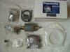
THE SYSTEM
I chose the Aquamist 2d system. The Aquamist 1s system uses only a single
pressure switch to determine when to inject water, and thus it is merely on or
off. Thus, the same volume of water is being injected regardless of RPM, or more
specifically regardless of the amount of Air or Fuel the car is consuming. In
the Aquamist 2d system, there is also a pressure sensor, so you can control a
limit that the system will not operate below. Once you are above that set point,
this system reads your fuel injector duty cycle and injects water at a fixed
ratio to your fuel. This method can ensure that you don't inject too much water
at lower RPMs or too little at higher RPMs. With either system, you can still
change the size of the injection jet, which will scale the amount of water
injected.
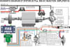
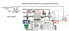
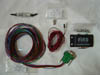
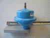
SYSTEM DESCRIPTION
See the first photo below. The left side of the diagram begins the system
with a water tank (I chose to use my washer fluid reservoir). Aquamist supplies
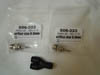
a threaded tubing connector for this connection. Water flows through the 6mm
tubing to the next item, the Water Filter. After that, it connects to the input
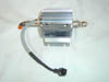
of the pump. The outlet side of the pump has 4mm tubing which goes to a Water
Pressure Switch. This switch tells the pump when it needs to operate in order to
maintain the desired water pressure in the line. After this, more 4mm tubing
connects to the High Speed Solenoid Valve. It is this valve that controls when
water is injected into the system. This valve is controlled by the Fuel
Injection Amplifier circuit which uses the Fuel Injector and the Boost Pressure
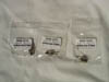
Switch to determine when to inject water (as described above). After this valve,
tubing connects to a Jet. In this section, I have inserted a Splitter to provide
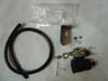
water to both halves of the bi-pipe. There is also a Yellow LED included which
connects to alert of a blocked water jet (or other flow obstruction). The
green LED flashes to the pulse of the fuel injectors and the Red LED illuminates
when water is being injected. I have also added a switch to turn the
system off when desired.
| |
|
|
|
|
| |
|
|
|
|
| |
|
|